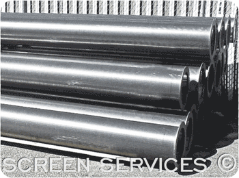
  Infiltration Galleries are capable of supplying large quantities of water, and are used where wells are unable to supply water needs, i.e.where an impermeable rock barrier affects well efficiency, or where surface water sources are too shallow for intake screens. Infiltration Galleries are capable of supplying large quantities of water, and are used where wells are unable to supply water needs, i.e.where an impermeable rock barrier affects well efficiency, or where surface water sources are too shallow for intake screens.
Infiltration galleries are one or more horizontal screens placed adjacent to (on-shore), or directly underneath (bed-mounted), a surface water source.

The decision whether to locate galleries on shore or under the water body must take into account several factors:
- Galleries located under the water source have higher yields. The yield will drop over time, however, as sedimentation reduces the hydraulic conductivity of the surrounding filter pack.
- Water is filtered more extensively for galleries located adjacent to the water source, and usually will be less turbid and have fewer bacteria.
- It is generally easier to install a gallery adjacent to the water source.
- Maintenance and repairs of on-shore galleries is easier. Bed-mounted galleries generally require more maintenance due to sedimentation.
- River meanders and lake level fluctuations can either uncover and wash away, or cover over with less permeable material, a bed-mounted gallery.

- Through-slot velocity should not be greater than 30.5mm per second.
- Axial velocity (flow inside the screen) should not be greater than 915mm per second. This avoids turbulent flow and air entrainment.
- The slot opening should be roughly half the smallest particle size of the gravel pack. Infiltration galleries are not effective at screening finer material from the flow.
- The gravel pack should have high permeability, and be of uniform size, clean and well-rounded.
- For fresh water applications, type 304 stainless steel is suitable. Type 316 stainless steel, or Monel, should be used in salt water.

- To reduce silt build-up, stream velocity should be a minimum of 300mm per second.
- The screen should be buried in the gravel pack between 1m and 1.5m below the stream bed surface.
- In multiple screen installations, screens should be placed a minimum of 3m apart.
- The filter pack should extend at least 1.5m on all sides of, and at least 0.3m below, the screens.
- All screens should include a backwash capability. The backwash rate should be twice the maximum pumping rate.

- The screen should be buried at least 1.2m beneath the static water level, but not more than 7.6m.
- To determine screen requirements the point of no drawndown must be found by using a series of observation wells.

- Robert E. Buss, The Johnson Driller's Journal, Third Quarter, 1981.
- Fletcher G. Driscoll, Groundwater and Wells, Second Edition, published by Johnson Filtration Systems Inc., St. Paul, MN 55112, 1986.
|


